

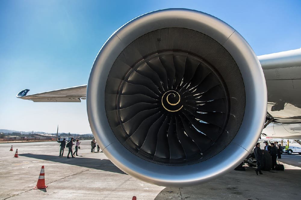
Turbofan Engine: Humanity’s Hardest Machine to Build
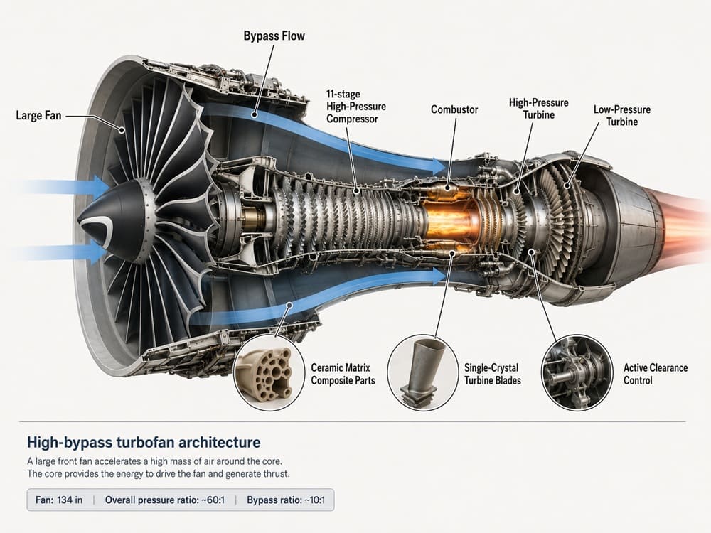
High-bypass turbofans push materials, aerodynamics, and manufacturing tolerances to their practical limits. GE Aerospace’s GE9X is the largest turbofan ever built and powers the Boeing 777X. Its fan measures 134 inches, or 3.4 metres, in diameter. It has an overall pressure ratio near 60:1 and a bypass ratio of about 10:1. The high-pressure core compresses air at 27:1 across eleven stages. Building these engines reliably and at scale may be harder than producing most other engineered systems.
They must operate safely for more than 30,000 flight hours, often under extreme conditions. Even spacecraft may present fewer combined challenges involving materials, precision, durability, and mass production. The market is worth tens of billions annually, yet entry barriers remain exceptionally high. This article explains why only GE, Rolls-Royce, and Pratt & Whitney dominate this specialised global industry. It examines the thermodynamics, metallurgy, and manufacturing statistics behind their advantage.
The Thermodynamic Wall: Brayton Cycle Limits
A turbofan’s core runs on the Brayton cycle. Thermal efficiency is governed by:
η_thermal = 1 − (1 / r_p^((γ−1)/γ))
where r_{p} is the total pressure ratio and \gamma \approx 1.4 for air. This looks simple, but every unit gain in r_p requires more compressor stages, tighter blade tip clearances, and hotter combustor exit temperatures, because compressing air adiabatically also heats it, as shown below:
T2/T1 = (P2/P1)^((γ−1)/γ)
The overall pressure ratio is 60:1, so the air entering the combustor is around 700°C before any fuel is added. The GE9X’s HPC has a pressure ratio of 27:1 by itself, and GE had to make the last stages of the HPC from powdered-metal nickel superalloy instead of regular forged titanium because the air temperature in the rear of the compressor was so high.
The net specific work output of the cycle is expressed as follows:
w_net = c_p·T1·[η_t ·T3/T1·(1 − r_p^−((γ−1)/γ)) − (r_p^((γ−1)/γ) − 1)/η_c]
where ηt and ηc are the isentropic efficiencies of the turbine and compressor, respectively. This single equation encompasses the entire engineering challenge. Every improvement in efficiency (η_t, η_c) or firing temperature (T₃) is at the cost of thrust and fuel burn. But each variable is limited by a different failure mode – creep, oxidation, flutter or surge.
The Turbine Inlet Temperature Problem
The combustor of a modern military engine such as the Pratt & Whitney F135 that powers the F-35 generates gas temperatures of more than 2,200°C (4,000°F), or some 800°C above the melting point of the nickel superalloys that form the turbine blades. The only reason the blades don’t melt is because of a combination of the following:
- Single-crystal casting: eliminates the grain boundaries, which are the weakest points of a polycrystalline metal under creep, by growing the entire blade as one single, unbroken crystal lattice through directional solidification, ensuring that the crystallographic growth axis is aligned with the principal stress axis according to Schmid’s Law.
- Thermal barrier coatings (TBCs): ceramic yttria-stabilised zirconia layers roughly 100–300 microns thick that impose a 100–150°C gradient across their depth.
- Internal film and impingement cooling: turbine blades are hollow castings containing serpentine internal passages, often with thousands of micro-holes under 0.5 mm in diameter, drilled by laser or EDM, bleeding compressor air across the blade surface to form a protective film layer.
Even the second-generation single-crystal superalloys brought about only a 40°C increase in usable temperature capability over the first-generation alloys – decades of metallurgy yielded only increments of tens of degrees. Put quite simply, TET (turbine inlet temperature) is the single most expensive number in aeropropulsion.
Rotordynamics and Tolerances
So if you take an engine like the GE9X , a big fan blade tip will be moving at relative speeds in the transonic to supersonic region. In engines like the F119, the LP shaft rotates at several thousand RPM and the HP shaft several thousand more, counter-rotating to cancel gyroscopic moments. The gaps between the moving blades and the stationary casing are fractions of a millimetre. If the fit is too loose, efficiency drops due to leakage; if it is too tight, thermal expansion can cause a rub that may destroy a stage in milliseconds.
Active clearance control systems bridge this gap by adjusting the casing cooling air in real time. Certification requires blade-out containment, i.e., the ability of an engine to withstand the release of a fan blade at its full rotational energy and not allow debris to penetrate the nacelle. The kinetic energy involved is enormous– — a GE9X fan blade departing at operating RPM has an energy equivalent to about that of a small car at highway speed — and the composite/Kevlar wound containment case has to absorb all of that.
Materials and Manufacturing Statistics
- The GE9X features ceramic matrix composites (CMC) in 65 components, the most of any commercial turbofan, able to run hundreds of degrees hotter than metal while weighing about a third of the weight. Each CMC part has a multi-week lay-up and sintering cycle and much less manufacturing tolerance for defects than metal casting.
- Fourth-generation carbon-fibre composite fan blades replace solid titanium forgings from a generation ago, a move made to save weight but one that took Rolls-Royce and GE more than a decade each to certify to bird-strike and blade-out standards.
- Designing a clean-sheet large civil turbofan costs billions of dollars (GE alone spent over $2 billion on the GE9X) and requires a certification and testing programme that takes years and thousands of hours of ground and flight testing before a single revenue flight.
Fighter Jet Engine Manufacturing: A Different, Harder Problem
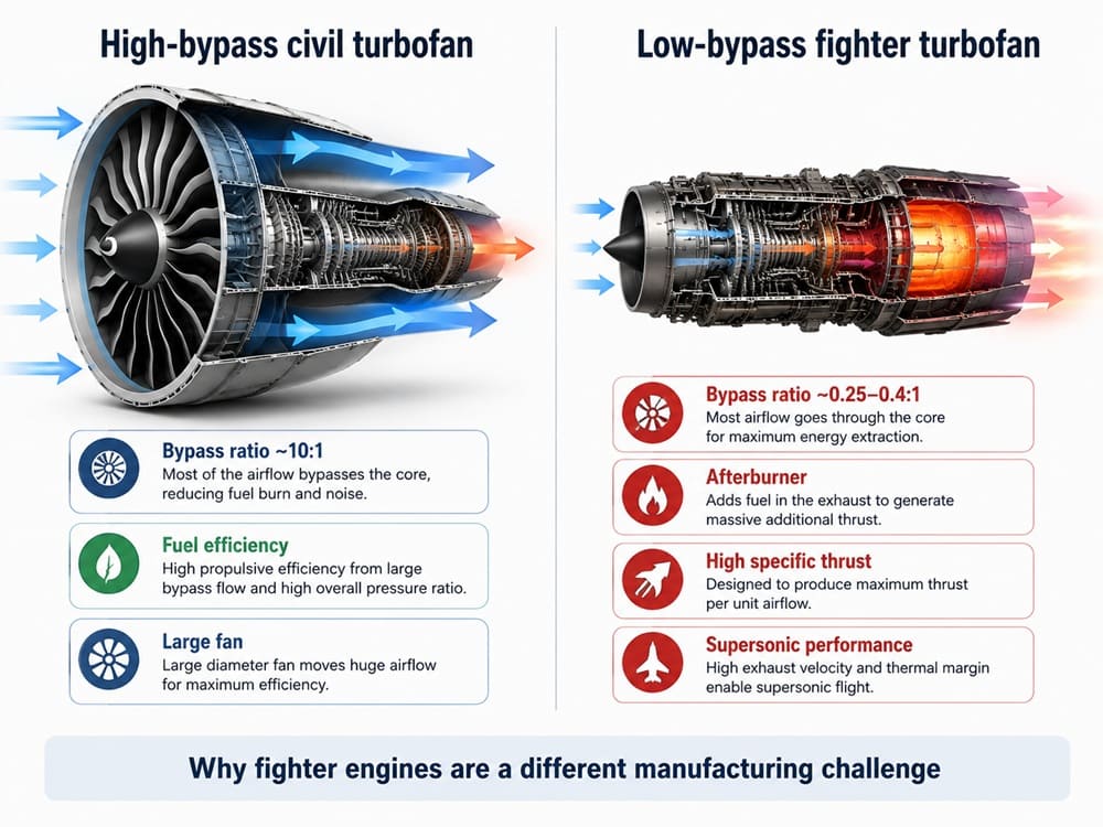
Military combat engines share the same core thermodynamics as civil turbofans but invert nearly every design priority, which makes them arguably the harder manufacturing challenge of the two.
Low bypass ratio, high specific thrust
The GE9X uses a high bypass ratio of about 10:1 to improve fuel efficiency. Fighter engines, however, operate with much lower bypass ratios. The Pratt & Whitney F119 powering the F-22 has a bypass ratio of about 0.3:1. The Eurojet EJ200 powering the Typhoon has a ratio of roughly 0.4:1. The General Electric F414 powering the Super Hornet operates near 0.25:1. Low bypass ratios sacrifice fuel economy in exchange for greater specific thrust. Specific thrust measures the thrust produced per unit of airflow. This allows fighters to accelerate rapidly and sustain supersonic flight. Consequently, the engine core works much harder for every pound of air. Its compressor and turbine stages often operate near their stress and temperature limits. They face these extreme demands throughout combat operations, not only at a steady cruise point.
Afterburning (reheat)
Injection and burning of additional fuel in the exhaust duct downstream of the turbine, where residual oxygen from the low-bypass core is still present, can increase thrust by 30-70% over dry (military) power. The F135 ranges from about 28,000 lbf dry to 43,000 lbf in full afterburner. The F414 gains nearly 70% over dry thrust in reheat. The afterburner liner and variable-area exhaust nozzle must endure thermal cycling from ambient to flame temperatures approaching 2,000°C in a fraction of a second, thousands of times during the service life of an engine. Civil engines never afterburn, so they never experience a fatigue environment like this.
Thrust-to-weight ratio as the design driver
Civil engines are optimised for thrust-specific fuel consumption (TSFC), while fighter engines are based on thrust-to-weight ratio (TWR) – the F119 has an impressive TWR of nearly 8–9:1, meaning it produces eight to nine times its weight in thrust. That ratio is the key, because it drives every casing, disc and blade down to the structural minimum – which is precisely why fighter engine cores are so much more failure-sensitive than a relatively conservative airliner core.
Thrust vectoring
The F119’s exhaust nozzles direct thrust up to ±20° in the pitch axis for manoeuvrability, adding an entire mechanical actuation system that operates in the hottest, most extreme-vibration part of the airframe – a subsystem that civil engines do not require.
Total Accumulated Cycles (TAC), not just hours
In the military, engine life is a function of accumulated stress cycles, not hours flown. An hour of steady cruise puts far less stress on the turbine disc than does a single throttle snap from idle to full afterburner in a dogfight. That means fighter-engine turbine discs and blades must be qualified for a much harsher low-cycle fatigue spectrum than a commercial engine, which has gentler and more predictable throttle excursions.
Smaller, hotter, more expensive per pound
A civil high-bypass fan distributes its mass flow over a large, relatively cool bypass stream. A fighter engine packs the same power into a much smaller diameter core, so the entire flow path runs hotter for its size. Then, when you add the single-crystal turbine blades, powder metallurgy discs, and the low production run of military programmes (hundreds or low thousands of engines compared to tens of thousands in a civil engine family), the unit costs and precision of machining requirements for fighter engines are much higher relative to their thrust output.
Fighter engine production, therefore, focuses the same metallurgical and aerodynamic issues of civil turbofans into a smaller, hotter and more cyclically abused package that also has to survive combat-representative throttle transients and, in engines like the F135’s STOVL variant for the F-35B, an additional shaft-driven lift fan clutch system that is totally alien to any civil design.
Why So Few Companies Can Do This
Despite strong demand, only a handful of companies build large civil or military turbofans at scale. These include GE Aerospace, Rolls-Royce, Pratt & Whitney, Eurojet, Safran, and Russia’s UEC-Saturn. Eurojet is a consortium involving Rolls-Royce, MTU, Safran, and ITP. Capital alone does not create the main barrier to entry. The real challenge is combining several highly specialised disciplines into a single production system. These include high-temperature metallurgy, transonic aerodynamics, rotordynamics, combustion chemistry, digital controls, and precision manufacturing.
Factories must maintain micron-level tolerances on components approaching the size of a small car. New entrants also need facilities capable of casting single-crystal turbine blades reliably. They require directional-solidification furnaces, advanced inspection systems, and tightly controlled manufacturing processes. Decades of proprietary alloy, coating, and cooling-hole data create another formidable barrier. Since the 1960s, most new competitors have failed to overcome this combination of knowledge, infrastructure, and experience.
Conclusion
Every discipline involved in turbofan development is possible to master. The challenge lies in applying every discipline simultaneously without compromising performance, safety, or reliability. Engineers must combine thermodynamics, high-temperature metallurgy, and manufacturing across both massive and microscopic scales. They must also use decades of proprietary materials, cooling, testing, and production data. Every component must function reliably for tens of thousands of operating hours. The engine must achieve this performance while carrying human lives under demanding conditions. Turbofans therefore represent engineering where scientists understand the physics exceptionally well. However, achieving the required tolerances, durability, and reliability remains extraordinarily difficult.
References
- GE Aerospace — GE9X Engine Specifications
Supports the fan diameter, bypass ratio, overall pressure ratio and composite fan-blade claims. - GE Aerospace — GE9X Certification Testing
Supports the 27:1, 11-stage high-pressure compressor and CMC applications. - Pratt & Whitney — F135 Engine Fast Facts
Supports the F135 intermediate and maximum thrust figures. - Rolls-Royce — Single-Crystal Turbine-Blade Technology
Supports single-crystal casting, internal cooling, laser-drilled holes and thermal-barrier coatings.
About the Author




I constantly emailed this weblog post page to all my
associates, as if like to read it afterward my links will too.
Hi there! I could have sworn I’ve been to this web site
before but after looking at a few of the posts I
realized it’s new to me. Regardless, I’m certainly delighted I
stumbled upon it and I’ll be book-marking it and checking back frequently!